This is part 2 of the story of building the best network simulator while working for Nokia. In part I I went through the problem and what options and tools we had in our disposal. In this part I’ll explain the requirements and some of the desig decisions.
Requirements
At that point we had our requirements laid out clearly. The simulation platform should:
- Be as configurable as possible to reduce the need for code changes for scenarios
- Run a simulated network with simulated nodes and channels
- Allow external virtual machines to be part of the simulation
- Have reporting captabilities
- Be able to run in a cluster
As we continued with those requirements we faced a problem we added another one to the list. If we have a virtual machine connected to the simulation, especially a discrete event simulation, time does not move at the same rate. This will not only cause tons of errors in our reports, but will heavily affect TCP congestion control. So unless we fix that problem, we just can’t have reliable tests.
- The platform should control the time rate of the machines to match that of the simulation.
Design Decisions
The platform uses ns3 at its core to simulate the virtual network. Although ns3 pretty much provided everything we needed, there were some bits and piece which needed to add. I’ll mention them when approperiate. For now let’s talk more about some high-level design decisions. Those are more or less “design requirements” which I set based on the previous requirements.
1. Inter-Component Communication In order to decouple the components from one another, the first design decision was to rely only on exchanging messages between them whenever possible. This was meant to allow the simulation itself to be distributed.
2. External Nodes As we mentioned we needed to allow external nodes to take part in the simulation. To achieve that, I had to allow any reachable device or virtual machine in the network to be able to just join the simulation at will. This generalization along with the previous point effectively reduced any node in the network to just an IP-MAC pair.
3. Traffic from/to Outside To simplify things even further, the platform really has no concept of an external node. When an external node joins the simulation, a special internal node is created which communicates with it. To explain this, if we had external nodes A and B, then within the platform we’d have A’ and B’. When A wants to send a message to B, A actaully wouldn’t know the IP address of B, it would only know that of B’, and the traffic flow will be
A: (A -> B') => (A' => B') => (A' => B) :B
A: (A <- B') <= (A' <= B') <= (A' <= B) :B
A sends a packet to B’, A’ actually receieves the message and changes its source to the internal IP address of A’. A’ then sends the packet to B’ which takes it and changes the destination to the IP address of B. B then replies to A’ and the process repeates itself.
4. Actually Passing Traffic to the Simulation The last decision was how to pass traffic from those external machines to the simulation without breaking anything? The answer was simple, change the routing table of the machine to send traffic through the machine hosting the simulation. Of course doing that manually would be ridiculous, so we had to introduce a tool which does that automatically when a machine joins the network.
5. Network Stack The last design requirement was to define what is going to be simulated and what is going to be real. From the network layer and up is real implementation, and anything below that is simulated.
Overall Architecture
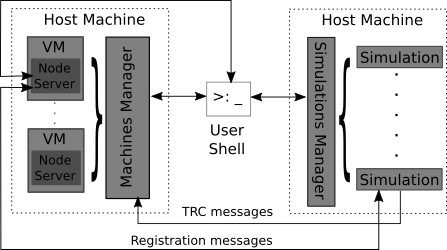
Now that we have laid out the requirements as the high-level design decisions, we can take a look at a high-level architecture. I only found those poor quality figures and I was too lazy to replicate them.

Here we have a machine (or machines) hosting a simulation (or simulations) and those simulations and managed by the simulation manager running on those machines. On the other side, we have virtual machines connected to a machines manager which controls them. Those virtual machines also need to have node servers running inside them as daemons. In the center of it all is a user shell which can be used to send commands to the simulations manager, machines manager, or node servers.
I’ll go deeper into those components in the next part but here’s an overview of each of the main components:
1. Node Server Not to be confused with a NodeJS server, this component handles three jobs: the registration process with a simulation, running scripts on events (including one to change the routing table), and writing and sending log files of network traces.
2. Machines Manager The job of the machines manager it to create, stop, remove, and configure virtual machines. I opted for using VirtualBox and the manager uses its Java SDK.
3. Simulations and Simulations Manager As mentioned before, we used ns3 to run the actual simulations. On top of that I added a simple manager to make the job of starting and stopping simulations easier.
Conclusion
We have had a look at the problem and some background, the requirements of the system and a high-level view of the architecture. Next I will go deeper into those components. Things will get a bit more interesting, and slightly more technical.