This is part 3 of the story of building the best network simulator while working for Nokia. In part II we had an overview of the design of the platform. In this part I will go a bit deeper into the internal components of the platform.
In the previous chapter, we mentioned that the three main parts of the platform were: the virtual machines manager, the node server, and the core simulation. Let’s now take a look at each one independently. This is an oversimplification of nearly 20 pages of documentation and three sections in a technical report. There are many points I didn’t mention here since they’re only of value to someone who is going to replicate the effort.
Machines Manager
Since virtual machines were the most suitable type of nodes, a hypervisor had to be chosen; and VirtualBox was the hypervisor of choice. VirtualBox comes with a variety of interfaces for its core modules, and it also provides an SDK to interact directly with its those modules.
The role of the manager was to automate the process of preparing, modifying, running and stopping, and controlling the virtual machines. This was also important for another reason. Assume that you have different scenarios with different traffic that you want to run, typically you might need to create an image for each. This is error prone, and makes maintaining those images a tedius task. We can leverage some of the features of VirtualBox to our advantage. You could create just a single image for all your scenarios and let the manager clone it. But the manager wouldn’t just clone it, it would use differencing disk, and configure the network settings properly for the scenario.
There’s a catch though, to allow for time rate control (more on that later), paravirtualization had to be disabled, otherwise KVM clock will interfer.
Node Server
The node server handles everything simulation-related in a machine: registering it in a simulation, running event scripts, and managing traces and logs. While the server can run anywhere, I added a unit file for it to make installing it when systemd is available easier. All the machines that we had were running a Linux distribution with systemd so that was a reasonable assumption.
Once the node server is running, it then awaits a request to make it register with
a simulation. This is typically done through the user shell. It will communicate
with the simulation server and provide all its interfaces. The simulation will do
some magic and send back the registered interfaces. Upon a successful registration,
the node server will trigger all the scripts registered for the start event.
The node server has three events: init, start, and stop. Shell or Python
scripts could be bound to those events. Those are essentially the scenario scripts.
So whan the server starts it’ll run init scripts. Then when it has joined a
simulation it’ll run the start scripts. And finally when the simulation stops
it’ll run the stop scripts.
For example, in one of the scenarios we wanted to have a file-serving server which
stored a large file and then clients could download that file. The server machines
had a script which ran on init event to start the server, and the clients had
a script which connects to a server and downloads the file on start event.
Core Simulation
This is the most important part of the platform, where the most of the magic takes place. As we mentioned, it was written based on ns3. The modular design of ns3 made it easy to add new components to it to support our use cases. But it was hardly just that part. Let’s take a look at its internal components.

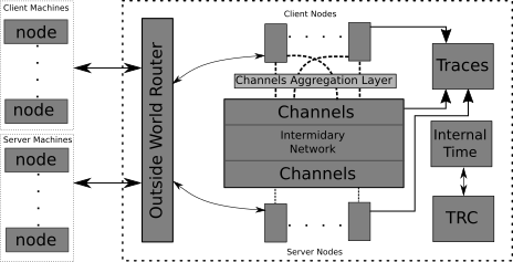
On the left we have our external nodes, the drivers of real traffic. We said that those machines interact with a simulation, but that was quite vague. As a matter of fact, they interact with the Outside World Router (OWR) of a simulation. In part II we also talked about changing the routing table of the node. This is precisely where we point the traffic to. So the OWR to the external nodes is what your home router is to your devices. The router works by binding a raw socket to an interfac on the system but other approaches are also possible; e.g. TAP devices could be used to achieve the same results. The router then filters out the packets which didn’t come from a registered node.

The server and client nodes shown at the top and bottom are just normal ns3 User Equipment (UE) nodes. But they no longer just interact with the simulated channels directly. We introduced a channel aggregation layer which allows some lower level multi-path to take place.
All UEs and channels write their network traces to a tracing module which flushes the traces to disk periodically or when a certain threshold is hit. And then there’s the Time Control Units (TRC) which we’ll talk more about in the next part.
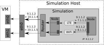
We also mentioned how we map the requests between external and simulated nodes, the following figure will give a more concrete example of that.

Conclusion
And just like that we now know how each of the main parts of the platform works. In the next part I’ll explain why it doesn’t actually “work”, what caused that problem and how it was fixed.